| MCC Technical Specifications: |
- Rated Service Voltage : 415 V
- Rated Frequency : 50 Hz
- Rated Insulation Voltage : 660 V
- Rated Current (maximum) : 4000 A
- Busbar Fault Level : 50 kA withstand (for 1 sec) 105 kA (Peak)
- Busbar System : TP-E or TPN-E
|
| |
| Degree of Protection: IP 54 AS PER IS 2147 |
| |
 |
| |
| Fully Compartmentalised:
Separate chambers for:
- Main Horizontal Busbars
- Droppers
- Control bus
- Feeder compartments
- Cables
|
| |
| Versions: |
- Single front
- Double front
|
| |
| Overall Dimensions (mm): S.F / D.F |
- Width 800 / 800
- Height 2375, 2475
- Depth 600 / 900
|
| |
| Maintenance Features: |
| Elecmech D/o MCC Panels are designed to be maintenance free. |
- Telescopic Rails & Racking Screw
- Positive guidance by Proven Rack and Screw arrangement
- Smooth movement of the module.
- Perfect alignment of contacts.
- No Banging of Busbars on insertion of modules.
- Eliminates the need to remove the module for routine checks / minor modifications.
- All identical drawout units are fully interchangeable thus minimizing downtime.
- Vertical T droppers minimizes the number of joints thus reducing heat losses and the number of joints to maintained.
- Tin-Copper Electroplated Aluminum T section Vertical Bus ensures that there is no direct Copper to Aluminum contact, ensuring no corrosion due to Cu to Al joint T Eletroplating of the T dropper elliminates additional Cop-al joint.
|
| |
| Facility for Padlocking: |
- Module in service and test position
- Power switches
|
| |
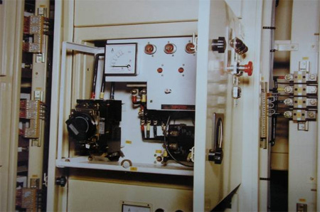
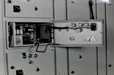
| Drawout feeder door: |
- Indicating lamps, push buttons, meters and selector switches are mounted on drawout feeder’s door.
- This door can be hinged out for inspection / maintenance of the connections.
- Only the d/o fdr door needs to be changed in case of change in specified control equipment.
|
| |
| Design Features: |
| |
-
Fully drawout module with 3 Service, Test & Isolated positions
|
- Service: Power & Control contacts engaged.
- Test: Control circuits can be tested. Power contacts disconnected.
- Isolated: Both power and control contacts disengaged. Access internal components without removing the module.
- Maintenance: Can be withdrawn for routine maintenance.
|
-
Silver plated drawout Contacts: Drawout power contacts are of Silver plated copper. They offer high resistance to abrasion, lower mV drop, leading to lower wear and tear and longer life of the contacts
- Programmable Sliding Contacts: Depending on logic requirements, programmed sliding contacts are used to permit selective signals during service, test position or to operate in both service and test positions.
|
| |
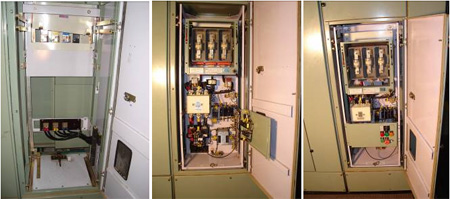
| Cable Alley: |
- The MCC is provided with large cabling area. The cable chamber width is 250 mm internally. Aluminium cables can therefore be easily accommodated and terminated.
Both top or bottom cable entry is possible.
- Gasket and Door lock:
Standard panels are provided with captive screws / Quarter turn knobs. However customized Panels can be provided with Alphabetical Key lockable doors to prevent un-authorized access to the cable alley.
- The cable alley doors are removable type. They are provided with Spring Loaded Quarter-turn locks operable by a special key or with quarter turn knobs.
|
| |
| Dimensions: |
- Height: 2375.
- Width : 550+250=800 mm
- Depth : Single front: 600 mm (base frame), 622 mm with front door
- Depth: double front 900 mm (base frame), 944 mm with front and rear doors
|
| |
 |
|
|
 |
| |
| Module Design: |
- Module size: Module size ranges from 1/8th to 1/2 in multiples of 75 mm.
- 225mm Module can accomodate: Switchfuse feeders & MCCB upto 63A
- 1/6th Modules accommodate DOL Starters upto 18.5 kW
- Spring Loaded position lock
- Variety of Feeders
Larger Starters DOL / SD starter upto 160 kW are accommodated in a combination of feeders such as ½ (900 mm) for contactors and OL relays + 1/4th for SFU (450mm)
- Incomers can be Switch-fuse upto 800 A or ACB upto 1600 A
|
| |
| Auxiliary Busbars: |
-
Upto 6 Sets control busses can be accommodated in the control bus chamber.
|
| |
| Safety Features: |
- Busbars and droppers are provided with heat shrunk PVC sleeving.
- The heat curing process ensures no voids or pinholes. Except at the Joints and Vertical dropper contact plates, the busbars are completely covered with insulating material.
- Sleeving also protects busbars against accidental contacts with hardware, tools and vermin. 'Click-fit' joint shrouds are provided to cover tap-offs and fish-plate joints.
- Thus there are very few possibilities of short circuit between phase and neutral or earth in the busbar chamber. The heat shrunk PVC Sleeving is provided in addition to the large clearances in the busbar zone.
|
| |
| Merits: |
- Secondary insulation protects against accidental contact with hardware, tools and vermin.
- Restricts the arc, in case of a fault, to the zone of initiation.
|
| |
| Busbar Supports: |
- Busbar supports are of SMC.
- This material has higher mechanical strength compared to conventional support material.
|
| |
| Safety Shutters: |
- Gravity operated safety shutters block access to the Vertical live T-droppers when the module is withdrawn from the service position.
|
| |
| Scraping Earth System: |
- Tinned Copper contacts on the fixed partition plate and d/o trolley ensures perfect earthing of d/o modules
|
| |
| Safety: Operator safety is ensured by: |
- Distinct vertical earth bar of full length for each panel front.
- Tinned Cu plated scraping earth contact on each drawout module of 'Make-first' and 'Break-last' type.
- All doors are individually earthed.
|
| |
 |
| |
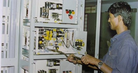
| Other MCC features |
`
- Elecmech Motor Control Centre is a free-standing and floor mounting type switchboard available both in single front and double front versions, suitable for indoor installation.
- To facilitate transportation, the MCC is split into multiple sections. Each section is wrapped in an HDPE cover and packed in a wooden crate case.
- To arrive at the approximate overall dimensions of the packing cases, add 300mm to the dimensions of the packing cases, add 300mm to the dimensions of the respective section.
- Each vertical panel is divided into distinct zones for busbars, feeders, power cabling and control busbars.
- Horizontal busbars (HBB) are located at the top of the panels. The phase sequence, from rear to front, is N-R-Y-B. Where the number of bars per phase exceeds two, the HBB is split into two packets per phase. The phase sequence is N-R1-Y1-B1-R2-Y2-B2 from rear to front.
- The droppers are located behind the module chamber and isolated from the unit compartment with an insulating barrier. The phase sequence, as seen from front left to right, is R-Y-B-N.
- Click-fit Busbar joint shrouds can be provided on the HBB for complete insulation. Shrouds can be easily removed for tightening the joints.
- Control bus, are located in the top-front chamber of the panel. In the double front MCCs, auxiliary busbars are placed in one of the fronts, and tap-offs are taken for feeders in both the fronts.
- The incoming power contacts are located on the right hand side, while the outgoing power contacts are located on the right hand side rear.
- The starter unit in the fully drawout version has the following positions:
- Connected (service) position
- Test position
- Disconnected (isolated) position
- The connected/test/disconnected positions are indicated by matching red lines on the bottom tray of the compartment and the red arrow mounted on the withdrawable unit.
- The control contacts, i.e. the Secondary Isolating Contacts (SICs) are mounted in 2 columns on the drawout module. The rear column comprises SIC making in “Service” position. The front column can have the following varieties of SICs:
- Service + Test
- Test only
- Service only
- For 225 and 300mm units, SICs can be located on LHS also.
- Such control terminals are duplicated in the cable alley. Wiring from the LHS SICs to the fixed terminals is factory-assembled and routed through a PVC duct mounted on the bottom side of upper tray for respective unit
- For 450 to 900 mm units. SIC are located on the right hand side only.
|